these steps are copied from cj-motorsports i put the steps here for reference when i do this myself.
Walbro GSS342 Installation (350z, G35, FX35, etc)
Note: Installation is intended for qualified individuals. This manual is not fully detailed, as some operations should be familiar for an experienced VQ35 Technician.
This is divided into 4 sections.
- The Pump
- Swirl Jet Modification
- Regulator Modification
- Final Assembly
Part 1: The Pump
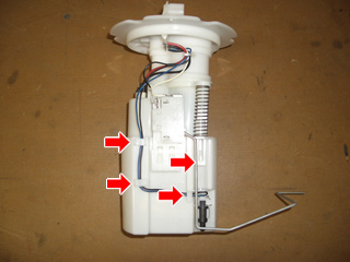
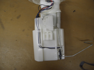
Remove the 2 wires from the 3 clips so that they are loose. Pull up the locking tab on the right so that you can gently pull the unit apart. Be careful not to pull too hard on the wiring.
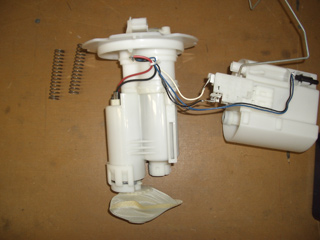
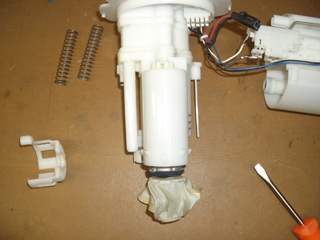
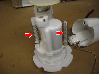
Place the 2 springs aside. The unit should look like this when separated.
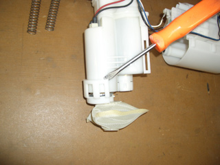
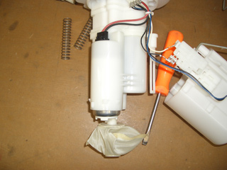
Use a screwdriver to pop the pump cap off the locks and remove the cap.
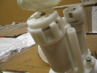
This is the unit with the cap removed.
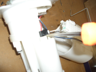
Remove the electrical connector from the pump.
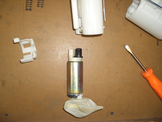
The pump is ready to slide out, downward.
Pump removed.
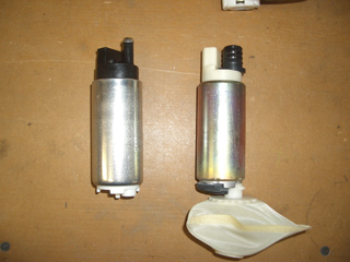
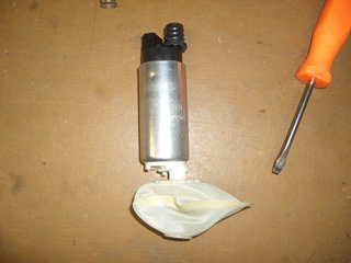
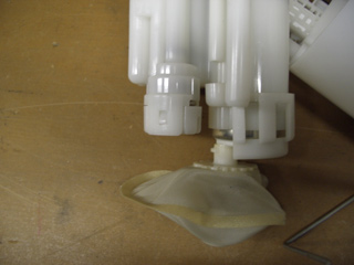
Walbro on the left, removed stock pump on the right.
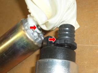
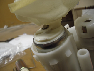
Swap the top seal to the Walbro (Right arrow). Remove the sock by focusing on removing the round metal lock (left arrow).
Put the sock on the Walbro, and put the metal lock on the Walbro. Be careful, the metal lock is hard to get back on, and very easy to loose if it gets away on you.
Slide the Walbro back into the assembly. Make sure you feel the top seal slide into its position. Plug back in the electrical connector.
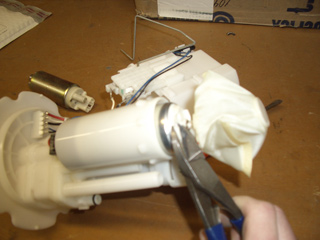
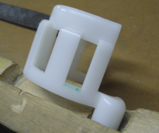
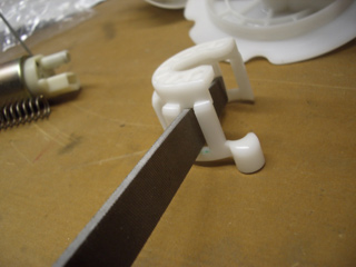
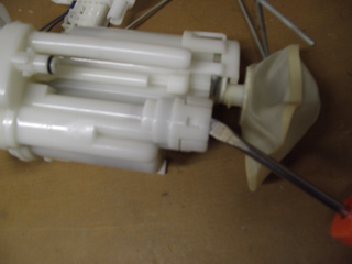
Use side-cutters to remove 3 of the 4 tabs on the bottom of the walbro (reference next picture for which 3 of the 4). Do not cut too deep or you will destroy the pump by opening a hole for it to leak. You want to cut them off almost flush. You are safer if you cut them high and file off the rest. Be cautious, the plastic cracks easily and if you crack it anywhere other than cracking the tabs off, the pump is ruined. You can even elect to file this all the way if you want to be extremely careful… filing it is messy so if you choose that route then take the pump back out so you don’t get a mess of plastic everywhere and use compressed air to blow clean the sock.
Pump with 3 tabs removed.
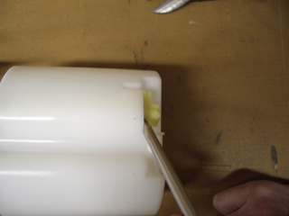
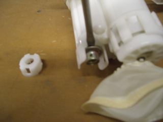
Mark this part of the pump cap to file off. Notice the green marking.
With some muscle, starting on the left and working your way to the right, re-install the pump cap onto all the locks. It can be done at this point but if you feel that you just cannot get it to snap and lock SECURELY on, you can file other sections down to allow more room. Just be careful, if you file too much then the pump will fit loosely, you want it extremely snug and you want to make sure the cap is correctly seated so that it does not pop off. It should be flexing just a little to get on.
Pump installation is now complete, however, do NOT skip the following steps for pressure control.
Part 2: Swirl Jet Modification Procedure (REQUIRED FOR GSS342 or larger pumps)
If this step is skipped, your idle and low RPM/Load fuel pressure will be high and cause tuning grief. This will address the issue and is required WITH or WITHOUT a return fuel system.
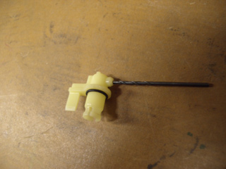
Carefully remove the yellow swirl jet from the bottom of the can. Do not break it, its just cheap plastic.
Drill the outlet to .070″. If you are using a larger pump like the DW or the Aeromotive, a .100″ might be a better idea. Its very soft plastic and drills easy, be careful not to drill all the way through the entire part or it is ruined and not replaceable. Just drill until you can look into the large opening and see the drill has made it to the chamber.
Making sure the o-ring is still in place, snap the jet back into the can. This step is complete. Follow the next step if you DO NOT have a return fuel system.
Part 3: Regulator Modification
If you are installing a return fuel system, then skip this entire step and begin installing the return correction kit. This modification is only needed if the OEM regulator is going to remain in place. Return fuel systems eliminate the OEM regulator.
Remove the regulator cap. Remember, its just plastic, dont break it.
Remove the regulator. Just put a screwdriver under the lip and twist, it pops out easy.
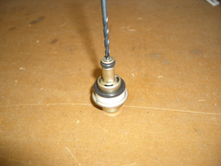
Using a 7/64 drill bit, open the regulator outlet oriface. ONLY drill until you make it thru the sheet metal.
Blow the regulator off with compressed air. Making sure both o-rings and the plastic spacer are in place, reinsert the regulator into the housing and re-install the regulator cap.
Part 4: Final Assembly
Reinstall the 2 assembly springs.
Reassemble the housing. It helps to use one hand to compress the filter sock. Don’t pull out the wiring. Make sure you get it all back into place and when done properly the housing can be compressed by hand and it will naturally fully extend to its natural position when you let it go. Re-secure the wires to the clips on the housing.
download the steps in PDF
350z_G35C; Fuel Pump Upgrade – CJ Motorsports Tech
